Attaching the Standard Wellhead
- CMT Multilevel Systems Main Page
- Get a Quote
- Send Me Info
- Why Multilevels?
- Datasheet
- Applications and Advantages of CMT
- Multichannel Tubing
- Seals and Sand Packs
- Multilevels are Essential
- Monitoring Options
- Field Applications
- Training Programs
- Download (PDF)
- Instructions
- CMT Multilevel System Assembly Manual
- Pre-Installation Requirements
- Introduction
- Preparation
- Assembling Standard CMT Systems
- Marking and Cutting the Tubing
- Cutting Outer Ports and Vent Holes
- Configuring Tubing Bottom
- Attaching Tubing Centralizers
- CMT Placement
- Attaching Standard Wellhead
- Optional Mult-Purge Manifold Assembly
- Monitoring Options
- CMT Specifications & Considerations
- Terms and Conditions
- Table of Contents
- Download (PDF)
- Narrow CMT Multilevel System Assembly Manual
- Pre-Installation Requirements
- Introduction
- Preparation
- Assembling Standard CMT Multilevel Systems
- Marking the CMT Tubing
- Cutting the Ports and Vent Hole
- Configuring the Bottom of the CMT Tubing
- Narrow CMT Placement
- Attaching the Standard Wellhead
- Optional Flow Control Monitoring Assembly
- Optional Multi-Purge Manifold Assembly
- CMT Installation with Sand and Bentonite Cartridges
- Installation Design Example
- Sand and Bentonite Cartridge Preparation
- Sand and Bentonite Cartridge Installation
- Narrow CMT Port Assembly
- Installing Narrow CMT Sand Cartridges
- Installing Narrow CMT Spring Cartridges
- CMT Multilevel System Monitoring Options
- Terms and Conditions
- Table of Contents
- Download (PDF)
- Purge/Grout Adaptor Operating Instructions
- Constructing Dual CMT Ports
- Summary of Drilling Methods and Techniques
- CMT Specifications and Considerations
- CMT Multilevel System Assembly Manual
- FAQ
- Trained CMT Contractors
- Technical Bulletins and Case Studies
- CMT for High Resolution Vapour Intrusion Monitoring
- Sampling in Multilevels: Options and Helpful Hints
- CMT Systems for the LUST Market
- CMT Vapor Monitoring
- Multilevel Systems
Water Quality Probes
Solinst Eureka, a global leader in the design and manufacture of multiparameter water quality sondes.
Solinst Field Services
Safeguard your project’s success and mitigate any potential for downtime or additional costs.
Step 21) Attach the Wellhead
Note:
The Solinst Tag Line, (Model 103), is recommended for accurate sand and bentonite placement.
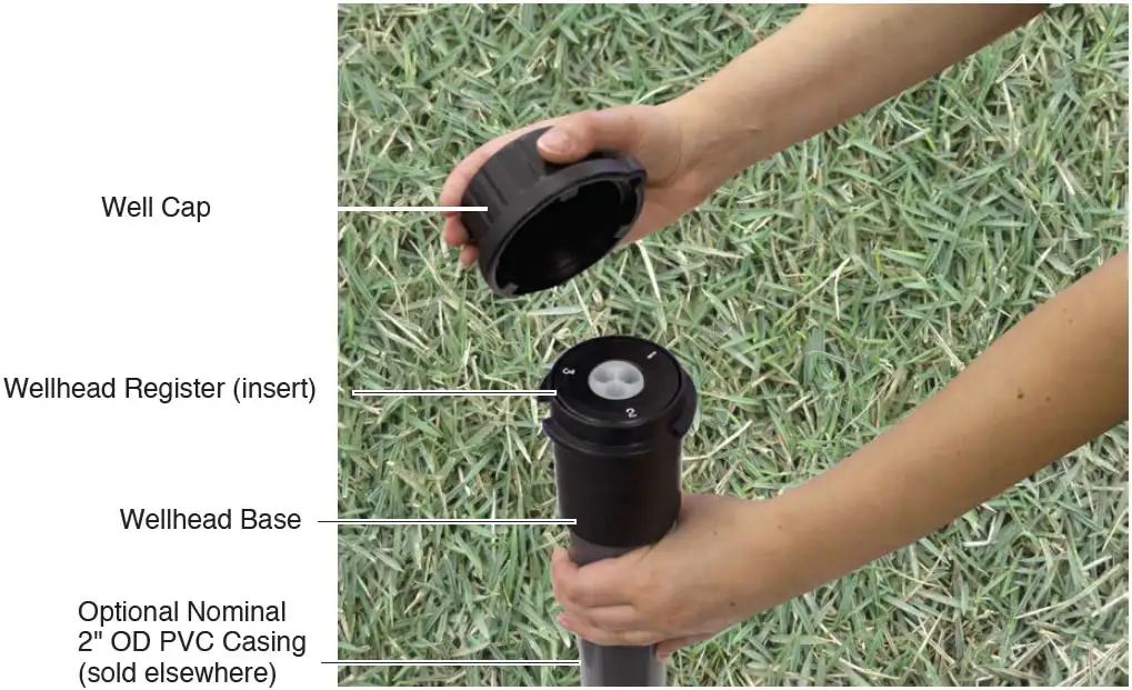
Figure 21 – Bring The Pvc Pipe Up So The CMT Multilevel System Register Seats In The Wellhead Base
After the well has been built, cut the CMT tubing to the final elevation. You may choose to finish your CMT installation above ground surface. If so, you can leave the CMT stick-up as is and install the standard wellhead register or “house” the CMT inside a cut length of 2″ dia. PVC riser pipe (not supplied).
If housing in a PVC pipe, first slide the PVC pipe over the CMT stick-up, and push below the final elevation of the CMT. Slide the wellhead base over the tubing and onto the PVC pipe. The wellhead base provides a tight friction fit on the PVC pipe.
Locate Channel 1 and slide the wellhead register over the tubing, flush with the end. Align the stamped number one on the register with the Channel 1 identifier marking on the outside of the tubing. Secure the wellhead register to the CMT tubing by tightening the hex screw on the side of the register using a 1/8″ Allen Key. Bring the PVC pipe up so the register seats in the wellhead base (Figure 21). Grout or cement the PVC pipe in place.