Installing Narrow CMT Sand Cartridges
- CMT Multilevel Systems Main Page
- Get a Quote
- Send Me Info
- Why Multilevels?
- Datasheet
- Applications and Advantages of CMT
- Multichannel Tubing
- Seals and Sand Packs
- Multilevels are Essential
- Monitoring Options
- Field Applications
- Training Programs
- Download (PDF)
- Instructions
- CMT Multilevel System Assembly Manual
- Pre-Installation Requirements
- Introduction
- Preparation
- Assembling Standard CMT Systems
- Marking and Cutting the Tubing
- Cutting Outer Ports and Vent Holes
- Configuring Tubing Bottom
- Attaching Tubing Centralizers
- CMT Placement
- Attaching Standard Wellhead
- Optional Mult-Purge Manifold Assembly
- Monitoring Options
- CMT Specifications & Considerations
- Terms and Conditions
- Table of Contents
- Download (PDF)
- Narrow CMT Multilevel System Assembly Manual
- Pre-Installation Requirements
- Introduction
- Preparation
- Assembling Standard CMT Multilevel Systems
- Marking the CMT Tubing
- Cutting the Ports and Vent Hole
- Configuring the Bottom of the CMT Tubing
- Narrow CMT Placement
- Attaching the Standard Wellhead
- Optional Flow Control Monitoring Assembly
- Optional Multi-Purge Manifold Assembly
- CMT Installation with Sand and Bentonite Cartridges
- Installation Design Example
- Sand and Bentonite Cartridge Preparation
- Sand and Bentonite Cartridge Installation
- Narrow CMT Port Assembly
- Installing Narrow CMT Sand Cartridges
- Installing Narrow CMT Spring Cartridges
- CMT Multilevel System Monitoring Options
- Terms and Conditions
- Table of Contents
- Download (PDF)
- Purge/Grout Adaptor Operating Instructions
- Constructing Dual CMT Ports
- Summary of Drilling Methods and Techniques
- CMT Specifications and Considerations
- CMT Multilevel System Assembly Manual
- FAQ
- Trained CMT Contractors
- Technical Bulletins and Case Studies
- CMT for High Resolution Vapour Intrusion Monitoring
- Sampling in Multilevels: Options and Helpful Hints
- CMT Systems for the LUST Market
- CMT Vapor Monitoring
- Multilevel Systems
Water Quality Probes
Solinst Eureka, a global leader in the design and manufacture of multiparameter water quality sondes.
Solinst Field Services
Safeguard your project’s success and mitigate any potential for downtime or additional costs.
Figure 29 shows everything required to construct a Sand Cartridge; PVC screen, sand, two black plugs (one as spare), two End Caps, Spacer, Separator Disk, and Gear Clamp.
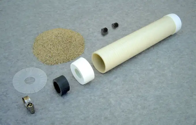
Figure 29 – CMT Multilevel System Sand Cartridge Setup
Note:
Remember to construct the CMT System from the middle port and work outward and towards the top and bottom. BELOW each Cartridge, slide on a Spacer, Separator Disk and Gear Clamp.
Push an End Cap onto the 2″ (50 mm) diameter screen and push the Feeder Tube all the way through the centre of the PVC screen. By hand, (see Figure 30) slowly add sand to the Sand Cartridge. Do NOT overfill the Sand Cartridge. Leave about 2″ (50 mm) of head space so as to ensure the assembly will slide along the CMT without creating too much friction. Once filled, add the other End Cap to the Sand Cartridge Assembly.
Remember to construct the CMT from the middle (Port 2 in our example) and work outward and towards Ports 1 and 3.
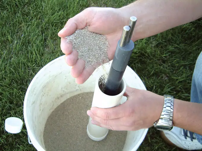
Figure 30 – Pouring Sand Into CMT Multilevel System Sand Cartridge
Insert the Feeder Tube and Key into the end of the CMT tubing. To prevent sand infiltration while placing the Sand Cartridge, use a black plug to block the vent hole. Slide the Sand Cartridge along the CMT over the screened port, and into position at Port 2 (see Figure 31). Do not forget to slide on a Gear Clamp, Separator Disk and Spacer. Use the supplied Torque Driver (12.5 in/lbs) and tighten the Gear Clamps.
Note:
Push a small black plastic plug into the vent hole below the port, to prevent sand draining out of the Sand Cartridge.
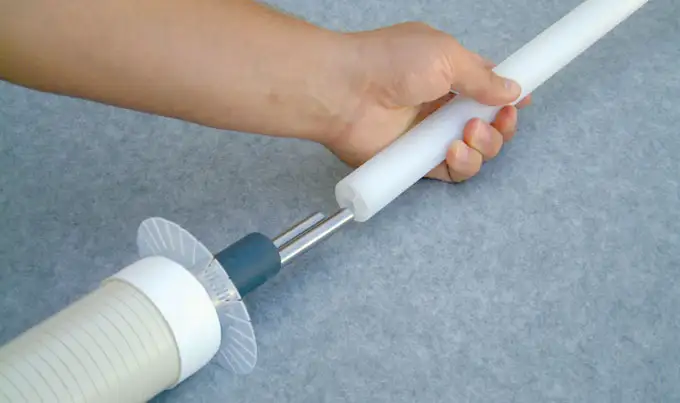
Figure 31