Optional Mult-Purge CMT Manifold Assembly
- CMT Multilevel Systems Main Page
- Get a Quote
- Send Me Info
- Why Multilevels?
- Datasheet
- Applications and Advantages of CMT
- Multichannel Tubing
- Seals and Sand Packs
- Multilevels are Essential
- Monitoring Options
- Field Applications
- Training Programs
- Download (PDF)
- Instructions
- CMT Multilevel System Assembly Manual
- Pre-Installation Requirements
- Introduction
- Preparation
- Assembling Standard CMT Systems
- Marking and Cutting the Tubing
- Cutting Outer Ports and Vent Holes
- Configuring Tubing Bottom
- Attaching Tubing Centralizers
- CMT Placement
- Attaching Standard Wellhead
- Optional Mult-Purge Manifold Assembly
- Monitoring Options
- CMT Specifications & Considerations
- Terms and Conditions
- Table of Contents
- Download (PDF)
- Narrow CMT Multilevel System Assembly Manual
- Pre-Installation Requirements
- Introduction
- Preparation
- Assembling Standard CMT Multilevel Systems
- Marking the CMT Tubing
- Cutting the Ports and Vent Hole
- Configuring the Bottom of the CMT Tubing
- Narrow CMT Placement
- Attaching the Standard Wellhead
- Optional Flow Control Monitoring Assembly
- Optional Multi-Purge Manifold Assembly
- CMT Installation with Sand and Bentonite Cartridges
- Installation Design Example
- Sand and Bentonite Cartridge Preparation
- Sand and Bentonite Cartridge Installation
- Narrow CMT Port Assembly
- Installing Narrow CMT Sand Cartridges
- Installing Narrow CMT Spring Cartridges
- CMT Multilevel System Monitoring Options
- Terms and Conditions
- Table of Contents
- Download (PDF)
- Purge/Grout Adaptor Operating Instructions
- Constructing Dual CMT Ports
- Summary of Drilling Methods and Techniques
- CMT Specifications and Considerations
- CMT Multilevel System Assembly Manual
- FAQ
- Trained CMT Contractors
- Technical Bulletins and Case Studies
- CMT for High Resolution Vapour Intrusion Monitoring
- Sampling in Multilevels: Options and Helpful Hints
- CMT Systems for the LUST Market
- CMT Vapor Monitoring
- Multilevel Systems
Trimeter
Three Parameters at
the Lowest Possible Cost
Solinst Field Services
Safeguard your project’s success and mitigate any potential for downtime or additional costs.
To purge and sample up to 4 Micro Double Valve Pumps, at a single location, a Multi-Purge Manifold Assembly is available.
- Mount the Multi-Purge Manifold over the well installation.
- Thread the pumps down through the collar opening in the Multi-Purge Manifold below the head assembly.
- Connect each individual pump manifold to the appropriately numbered Multi- Purge Manifold connection by pushing the male LL10 connector (on the pump manifold) into the brass quick connect fitting (on the assembly) while pulling back the brass sleeve on the fitting.
- Connect the compressed gas source/controller to the Multi-Purge connection at the top of the head assembly, using the same method as described in step 3.
- Open and adjust valves on the head assembly of the Multi-Purge Manifold for those pumps that require purging/sampling. Operate control box according to the instructions provided.
Note:
Airflow adjustments are made using the valves on the top of the head assembly of the manifold. A clockwise turn reduces air supply, counter-clockwise increases the air supply. If a valve is all the way down, it is in the off position. Valves can be adjusted by hand, but if they are too tight, a slot head screwdriver can be used.
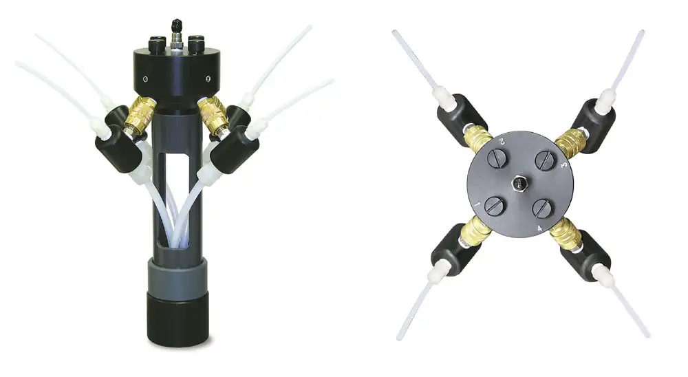
Figure 33 – Solinst 408M Micro Double Valve Pump Multipurge Manifold