Operating Principles
When the Solinst Bladder Pump is placed in a well or borehole, water rises inside the bladder and sample tubing to static level. Compressed nitrogen or air is supplied to the pump via the drive tubing using a Control Unit. Applying pressure causes the bladder to compress and closes the bottom check valve, forcing water from the bladder into the sample tubing.
During a vent cycle the pressure is released from the drive tubing. The bladder returns to its initial state as water re-enters the pump, while the top check valve prevents water already in the sample tubing from falling back into the bladder. Cycling the drive and vent provides water flow, the rate of which can be adjusted for purging or sampling.
Notes:
- The maximum depth for PVC Bladder Pump operation is 30 m (100 ft) below grade.
- DO NOT exceed an operating pressure of 50 psi.
- An external filter (pt#112832) is recommended if using a compressor to operate the Bladder Pump
- Tube fittings are based on use of 1/4" drive line and 1/4" sample line.
Pump Operation
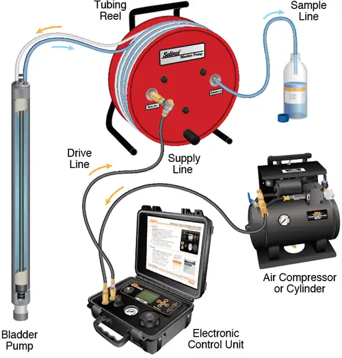
Portable: The pump will be attached to skip-bonded, dual 1/4" OD tubing, mounted on a reel.
- Push the drive and sample tubing over the tubing barbs on the stems, identified by an "S" and a "D" etched on the pump.
- Lower the assembled Bladder Pump into the well, using a safety line connected to the eye bolt on the pump. Kevlar cord or the Solinst Model 103 Tag Line can be used for this purpose.
- Connect the supply line with the in-line dryer from the compressed gas source to the Control Unit. The drive line connects from the Control Unit to the reel (drive and supply lines come with the Model 464 Control Unit).
- Attach a short (3 ft. or 1 m) length of 1/4" OD sample line to the sample connector on the reel.
Note:
If required, use an awl to open the very tip of the tubing, or heat the tubing to help push it completely over all the barbs.
For detailed pumping instructions, please see the Solinst Model 464 Control Unit Operating Instructions.
Dedicated: The pump will come with a roll(s) of tubing to be cut to length, as required, for attachment to a Wellhead.
- Cut the tubing to desired length. Push the drive and sample tubing over the tubing barbs on the stems, identified by an "S" and a "D" etched on the pump.
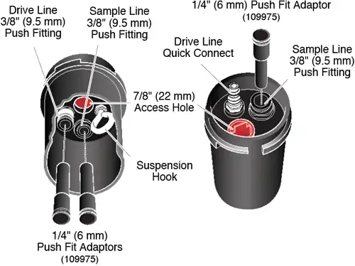
- Attach the sample line and drive line to the appropriate push fitting on the underside of the Wellhead (see diagram for use of push fittings and adaptors).
- Lower the Bladder Pump into the well, using a safety line if desired. If useful, attach the safety line to the suspension hook on the underside of the Wellhead. Push the Wellhead down firmly onto the riser casing.
- Connect the supply line with the in-line dryer from the compressed gas source to the Control Unit. The drive line connects from the Control Unit to the Wellhead (drive and supply lines come with the Model 464 Control Unit).
- Attach a short (3 ft. or 1 m) length of 3/8" OD sample line to the sample connector on the Wellhead (see diagram for use of push fitting and adaptor).
Note:
If required, use an awl to open the very tip of the tubing, or heat the tubing to help push it completely over all the barbs.
For detailed pumping instructions, please see the Solinst Model 464 Control Unit Operating Instructions.
Portable Sampling Setup

Dedicated Wellhead Setup (110227)


Wellheads come with three 1/4" push fit adaptors so that either 1/4" or 3/8" tubing can be used, as preferred.
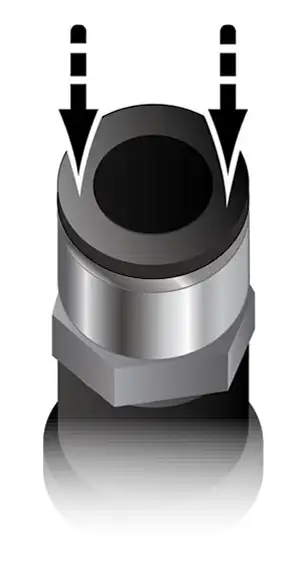
To attach tubing just push into push fitting. To release tubing push down on both sides of the top ring and pull tubing out.
Optional Drive Line Adaptor (107117)
Drive Line "M Style" Quick Connect

Drive Line 1/4" (6.4 mm) Push Fitting
When the Bladder Pump is deployed without a Wellhead or Tubing Reel, use a Drive Line Adaptor to allow the connection of the drive line quick connect fitting from the Control Unit to the drive line pump tubing.


