The LevelSender 5 is designed to be conveniently installed in a 2" well casing (4" with an adaptor). However, other installations are acceptable, if proper precautions are followed.
The LevelSender 5 has an IP rating of 67 (dust proof and can withstand immersion up to 1 meter depth for up to 30 minutes), so should not be submerged for longer periods. The operating temperature range is -20 to 60ºC.
You should have already installed the SIM card and batteries before configuring the LevelSender 5 using the PC Software, as well as the antenna (see Section 2).
Note:
You may want to consider the use of an extended top cap style protective well head. This would allow full access to the LevelSender components at the top of the monitoring well. If made of a plastic, it would eliminate signal interference that protective metal casing can cause.
6.1 Installing a LevelSender in a Well
Each LevelSender 5 station comes with a 2" Well Cap Assembly and a Support Hanger Bracket. To accommodate 4" wells, an optional adaptor is available for use with the 2" well cap base.
The Support Hanger Bracket is recommended to add extra security to the Reader Cable(s) when deployed.
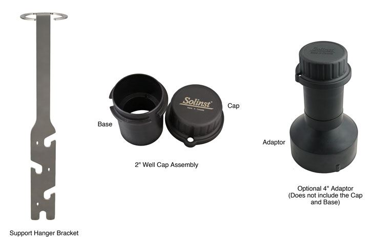
Figure 6-1 LevelSender 5 Installation Accessories
The following is the recommended method for installing a LevelSender 5 in a 2" well:
- If you are connecting a LevelSender to a Levelogger already installed in the field with a Direct Read Cable and Solinst Well Cap Assembly, you will need to remove the installation from the well. You may save the well cap base, but you do not need the well cap insert.
Note:
Each LevelSender comes with a 2" Well Cap Assembly, without the insert.
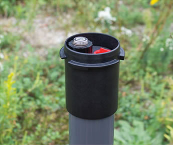
Remove Existing Levelogger Installation
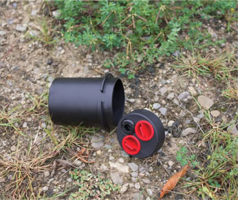
Remove the Well Cap Insert from the Well Cap Base
Figure 6-2 Remove Existing Installation
Note:
If you are installing a Levelogger and a Barologger in the same well, you will need a splitter to connect both dataloggers to the LevelSender. See Section 2.4.1.
- Install the well cap base on the well casing.
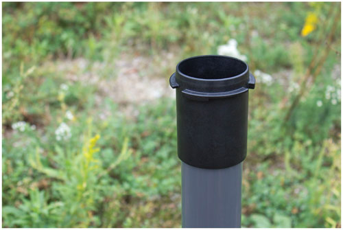
Figure 6-3 Install the Well Cap Base
- Wrap the Reader Cable around the Support Hanger Bracket, similar to what is shown in the photo below, leaving about 6" of slack above the top of the bracket. Use zip ties to secure the cable to the bracket.
Note:
Providing enough slack above the bracket allows you to lift the LevelSender from the well cap base to make room for a Water Level Meter for periodic depth to water measurements, without disturbing the datalogger(s) from their downhole position.
If installing a Barologger, secure the second Reader Cable to the Support Hanger Bracket using the same method.
The length of Reader Cable wrapped around the Support Hanger Bracket will depend on your application. If you are installing a Barologger in the same well, the Reader Cable/Direct Read Cable connection will need to be staggered from the Leveloggers connection in order to fit in a 2" well casing. Staggering the connections also allows more space for a Water Level Meter for periodic manual depth to water measurements. See Section 6.2.
Note:
Ensure the weight of the reader cable is not resting on a zip tie, but instead supported by one of the cutouts in the bracket.
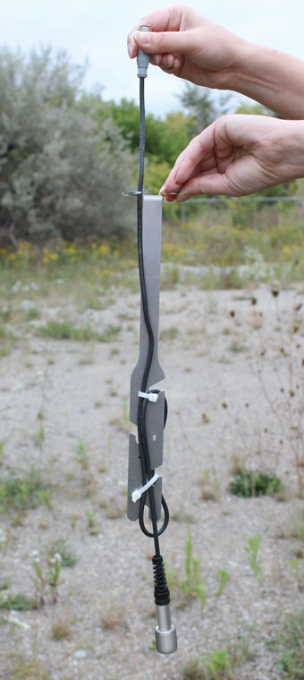
Figure 6-4 Secure the Reader Cable to the Support Hanger Bracket
- Connect the Levelogger to the Direct Read Cable (see Levelogger User Guide for more information, if required). Connect the Direct Read Cable to the Reader Cable. See Section 2.4 for more details. Slowly lower the datalogger(s) down the well.
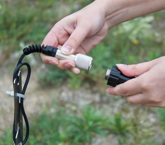
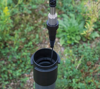
Figure 6-5 Connect the Direct Read Cable and Levelogger
- Lower the assembly until the Support Hanger Bracket seats on the shoulder in the well cap base.
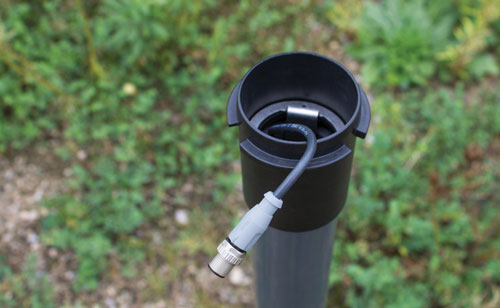
Figure 6-6 Lower the Assembly into the Well
Note:
There are three holes in the top of the Support Hanger Bracket the can be used to secure it in the well cap base with flat head screws.
- Connect the top end of the Reader Cable to the LevelSender (or Splitter). See Section 2.4 for more details.
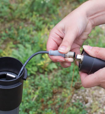
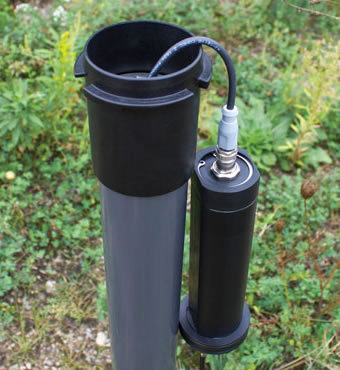
Figure 6-7 Connect the Reader Cable to the LevelSender
Note:
Providing enough slack at the top of the well allows you to lift the LevelSender from the well cap base, in order to make room for a Water Level Meter for periodic depth to water measurements, without disturbing the datalogger(s) from the downhole position.
- Carefully push the excess Reader Cable(s) into the well, while lowering the LevelSender into position. The LevelSender has flat sides so it fits alongside the Support Hanger Bracket. The LevelSender will seat on the shoulder in the well cap base.
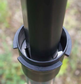
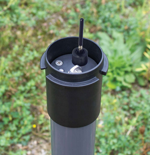
Figure 6-8 Lower the LevelSender into Position
- With the antenna in a bent position, you can install the well cap onto the well cap base.
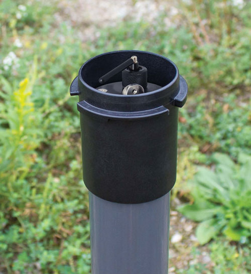
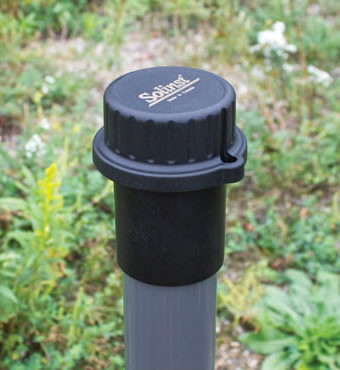
Figure 6-9 Install the Well Cap
Note:
See the Levelogger User Guide for more specific details on installing Leveloggers and Barologgers.
6.2 Levelogger Installation Examples

Figure 6-10 Single Levelogger Installation
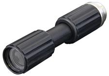
L5 Threaded Adaptor

Figure 6-11 Levelogger and Barologger Installation (Reader Cable Connections Staggered)
Note:
When installing a Barologger, an L5 Threaded Adaptor can be used in place of a Direct Read Cable, if extra cable length is not required. However, keep in mind, It is always recommended to install a Barologger in a similar thermal environment as the Levelogger, and should be suspended beyond the frost line and deep enough to avoid large temperature fluctuations.
6.3 LevelVent Installation
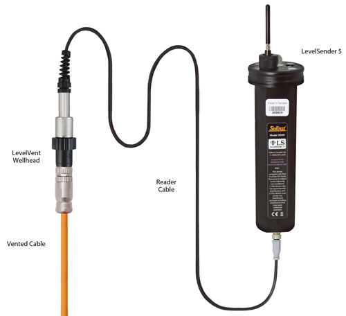
Figure 6-12 LevelVent Installation
Note:
See the Vented Dataloggers User Guide for more specific details on proper installation of the LevelVent.
6.4 Signal Strength and Antenna Considerations
You should consider testing the cellular strength at the site before installing your LevelSender. You can use your cellular phone to get an idea.
In general:
1-2 bars means there may be issues with data transmission. You may want to consider an alternate antenna, or adding an antenna extension cable so you can install it outside the enclosure you are using. You may also want to consider moving to a location with a better signal on site.
Note:
The type of enclosure planned for the LevelSender could affect the signal strength, e.g. a steel protective well casing can cause signal interference. Mounting the antenna on the outside of the enclosure could resolve this.
3-4 bars is good to excellent strength — there should not be any transmission problems.
6.4.1 Optional Antenna
If a higher gain antenna is required, Solinst offers a LTE Omni wall/pole mount antenna (790–860MHz, 1710–2690MHz and 3400–3800MHz) with a N (female) connector. It is connected to the LevelSender using a 10 ft antenna cable (RG-174 – SMA male to N type male plug). See section 2.1.2 for instructions to access the antenna connection on the LevelSender. The antenna assembly comes with a mounting bracket and gear clamps for connection to a pole/wall or installation of your choice.
Solinst also offers a recommended antenna cable seal kit for ensuring an IP68 rating when using this alternate antenna and cable. See separate full instructions for installing with the seal kit.
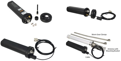
Figure 6-13 Connecting an External Antenna with Cable


