Note:
See the Vented Dataloggers User Guide for detailed AquaVent installation Instructions.
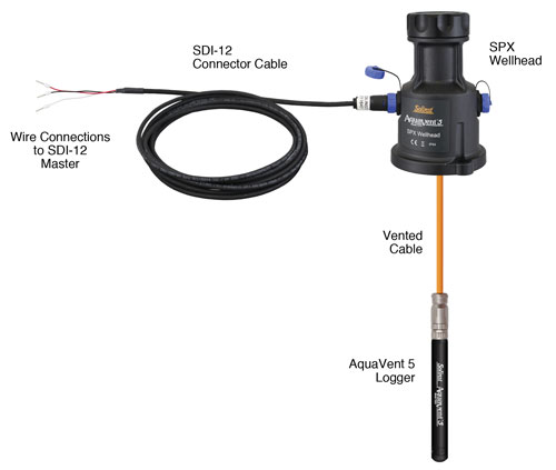
- Be sure that an AquaVent logger is properly connected to the SPX Wellhead using a Vented Cable.
- Turn off the power to the SDI-12 master and/or the SDI-12 network.
- From the SDI-12 Connector Cable, take the black ground wire and connect it to the master ground terminal; take the white signal wire and connect it to the SDI-12 data signal wire of the master; take the red wire and connect it to the 12 VDC power supply of the master or SDI-12 network.
- Be sure the SDI-12 Connector Cable is connected to the SPX Wellhead. (Ensure you have unplugged the USB Connector Cable after programming the AquaVent with Levelogger Software).
- Turn on power to the SDI-12 master and/or the SDI-12 network such that power is applied to the SDI-12 Connector Cable. The SPX Wellhead LED should emit the following signals in order:
- Tricolour spin (3 cycles) to indicate a power-on event.
- Alternating Yellow/Green for 10 rapid cycles indicate that AquaVent communication has been established, the SDI-12 device address has been set to represent that AquaVent, and the SDI-12 interface is online.
- Alternating Yellow/Red for 10 rapid cycles means that communication was NOT established, so the SDI-12 interface has been brought online using the default device address of ASCII '0'. (Check the AquaVent logger connections).
- The SPX Wellhead and the AquaVent logger are physically and properly hooked up to the SDI-12 master and the SDI-12 network.

Figure 3-3 AquaVent SDI-12 Installation


